Mosfet Enhancement And Depletion Mode
- Mosfet Characteristics In Enhancement And Depletion Mode Pdf
- Mosfet Characteristics In Enhancement And Depletion Mode
- What Is The Difference Between Enhancement And Depletion Mosfet
- Mosfet Enhancement And Depletion Mode
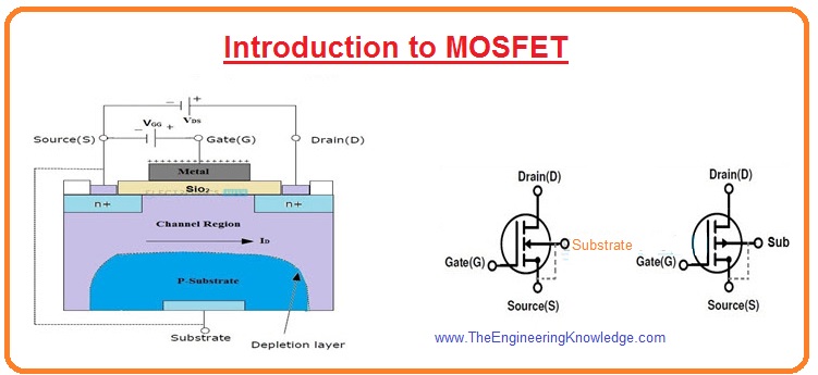
The MOSFET, Metal Oxide Semiconductor Field Effect Transistor or FET has an oxide film between the gate and the channel to increase the input impedance and reduce the overall circuit current. DMP22D6UT, P-CHANNEL ENHANCEMENT MODE MOSFET.
Gregory Mirsky
Company of heroes 2 - case blue mission pack. EDN
Many switch-mode power supplies use “kick-start” circuits to initialize their offline operation. These circuits may be simple resistors, such as IRIS4015, or more complicated arrangements built with bipolar transistors or MOSFETs. These transistors provide the initial current for the flyback or PFC (power-factor-correction) IC. When such a power supply starts operating in normal mode, a supply voltage from a dedicated winding keeps supplying the PFC IC, thus reducing power consumption of the kick-start circuitry.
Such schemes reduce – but do not eliminate – the power consumption of the kick-start circuitry, because the active component is usually a high-voltage bipolar transistor or high-voltage enhancement-mode MOSFET. These transistors’ base or gate requires forward-biasing with respect to the emitter or the source for normal operation. Therefore, a power loss always occurs in the circuits that keep the transistors in the off state. Unfortunately, engineers pay too little attention to depletion-mode MOSFETs, which require no forward-biasing for normal operation and, moreover, require gate potentials below the source. These valuable properties of depletion-mode MOSFETs suit them for a role in no-loss kick-start circuits for power supplies.
Figure 1 shows a conventional PFC circuit whose IC initially receives power from the output through a depletion-mode MOSFET, Q2, a DN2470. Q2’s source feeds PFC IC1 with an initial supply current of approximately 10 to 15 mA or less depending on the IC model. A brief power dissipation of approximately 4 to 6 W can do no harm to the MOSFET soldered to a copper pour. If you have concerns about the MOSFET’s health, you can use an IXTY02N50D. Resistors R3 and R4 set up Q2’s working point to obtain the minimum required current. Zener diode D5 limits voltage across IC1 to approximately 15 V for an input voltage of 18 V, which is usually necessary for most PFC ICs and is less than the maximum for MOSFET Q2.
| Figure 1. | A depletion-mode, high-voltage MOSFET provides a kick-start for a PFC IC. During normal operation, the MOSFET switches off and dissipates negligible power. |
When IC1 starts working normally, the secondary winding of the PFC inductor, L, generates the IC’s supply voltage, which diodes D1 and D3 and capacitors C1 and C2 condition. Transistor Q2 keeps feeding zener diode D5 and IC1 for a short interval. Eventually, bipolar transistor Q3 gets its base supply through resistor R5 from diode D2, turning on and clamping Q2’s gate to ground. Q3’s power source is the IC’s positive-supply potential of approximately 15 V, which is more than enough to shut off Q2. The residual thermal current of 10 to 20 µA produces no substantial power loss.

Materials on the topic
A P-Channel MOSFET is a type of MOSFET in which the channel of the MOSFET is composed of a majority of holes as current carriers. When the MOSFET is activated and is on, the majority of the current flowing are holes moving through the channels.
This is in contrast to the other type of MOSFET, which are N-Channel MOSFETs, in which the majority ofcurrent carriers are electrons.
Before, we go over the construction of P-Channel MOSFETs, we must go over the 2 types that exist. There are 2 types of P-Channel MOSFETs, enhancement-type MOSFETs and depletion-type MOSFETs.
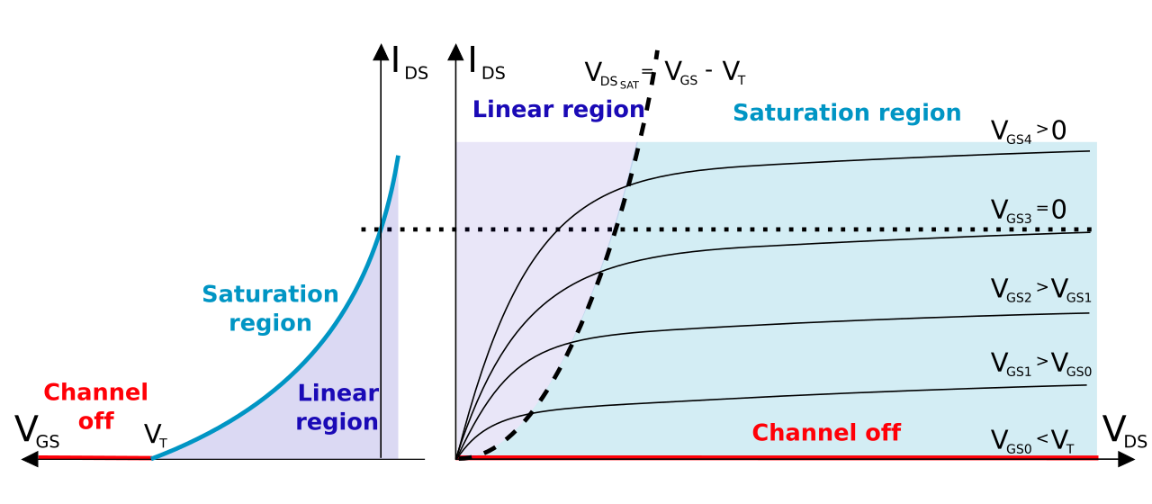
A depletion-type MOSFET is normally on (maximum current flows from source to drain) when no differencein voltage exists between the gate and source terminals. Customer data management software. However, if a voltage is applied to its gate lead, the drain-source channel becomes more resistive, until the gate voltage is so high, the transistor completely shuts off. An enhancement-type MOSFET is the opposite. It is normally off when the gate-source voltage is 0V(VGS=0). However, if a voltage is applied to its gate lead, the drain-source channel becomesless resistive.
In this article, we will go over how both P-Channel enhancement-type and depletion-type MOSFETs are constructed and operate.
How P-Channel MOSFETs Are Constructed Internally
An P-Channel MOSFET is made up of a P channel, which is a channel composed of a majority of hole current carriers. The gate terminals are made up of N-type material.
Depending on the voltage quantity and type (negative or positive)determines how the transistor operates and whether it turns on or off.


Mosfet Characteristics In Enhancement And Depletion Mode Pdf
How a P-Channel Enhancement-type MOSFET Works
How to Turn on a P-Channel Enhancement Type MOSFET
To turn on a P-Channel Enhancement-type MOSFET, apply a positive voltage VS to the source of the MOSFET and apply a negative voltage to the gate terminal of the MOSFET (the gate must be sufficiently more negative than the threshold voltage across the drain-source region(VG
So with a sufficient positive voltage, VS, to the source and load, and sufficient negative voltage applied to the gate, the P-Channel Enhancement-type MOSFET is fully functional and is in the active 'ON' mode of operation.

How to Turn Off a P-Channel Enhancement Type MOSFET
Mosfet Characteristics In Enhancement And Depletion Mode
To turn off a P-channel enhancement type MOSFET, there are 2 steps you can take. You can either cut off the bias positive voltage, VS, that powers the source. Or you can turn off the negative voltagegoing to the gate of the transistor.
How a P-Channel Depletion-type MOSFET Works
How to Turn on a P-Channel Depletion Type MOSFET
To turn on a P-Channel Depletion-Type MOSFET, for maximum operation, the gate voltage feeding the gate terminal should be 0V. With the gate voltage being 0V, the drain current is at is largest value and the transistor is in the active 'ON'region of conduction. Moorhuhn kart download.
So, again, to turn on a P channel depletion-type MOSFET, positive voltage is applied to the source of the p-channel MOSFET. So we power the source terminal of the MOSFET with VS, a positive voltage supply. With a sufficient positive voltage, VS, and no voltage (0V) applied to the base, the P-channel Depletion-type MOSFET is in maximum operation and has the largest current.
How to Turn Off a P-Channel Depletion Type MOSFET
To turn off a P-channel MOSFET, there are 2 steps you can take. You can either cut off the bias positivevoltage, VDD, that powers the drain. Or you can apply a negative voltage to the gate. When a negativevoltage is applied to the gate, the current is reduced. As the gate voltage, VG, becomes more negative, the current lessens until cutoff, which is when then MOSFET is in the 'OFF' condition. This stops a large source-drain current.
So ,again, as negative voltage is applied to the gate terminal of the P channel depletion-type MOSFET, the MOSFET conducts less and less current across the source-drain terminal. When the gate voltage reaches a certain negative voltage threshold, it shuts the transistor off. Negative voltage shuts the transistor off. This is for a depletion-type P-channel MOSFET.
MOSFET transistors are used for both switching and amplifying applications. MOSFETs are perhaps the most popular transistors used today. Their high input impedance makes them draw very little input current, they are easy to make, can be made very small, and consume very little power.
What Is The Difference Between Enhancement And Depletion Mosfet
Related Resources
How to Build a P-Channel MOSFET Switch Circuit
N-Channel MOSFET Basics
N Channel JFET Basics
P Channel JFET Basics
Types of Transistors
Mosfet Enhancement And Depletion Mode
